@kcorrie4
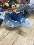
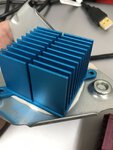
The primary heat rejection path is through the board and into the metal base plate of the EKP. I suggest changing the gap pad as outlined below. You may or may not want to add a heat sink.
So I am still gronking the write-up and the spreadsheet. I made a variety of changes to the spreadsheet (which I hope are correct) and help clarify the compare/contrast on the data. So here are my questions: Why did BMW move to the EKPM3? Are there benefits to which we are unaware, in the...

bmw.spoolstreet.com
This applies to both EKPM2 and EKPM3. The EKPM2 has been found to waste less power as heat and would be the module I recommend with aftermarket pumps. The EKPM3 HW 04 appears to have a better layout from a heat rejection standpoint than the EKPM3 HW 06.
If you do choose active cooling, the holes for letting the air out should be towards the end of the module with the connector. That is where the heat generating components are. In the EKP those components are the inductor and the switch. Looking at the board, you will see large copper areas on the top of the board (light green).
See
here. Notice the area near the connector has large copper "fills". This is for both heat and electrical current flow. The HW06 is more compressed and has a greater proportion of fill area, but the power generating components are still on the half of the board closest to the connector.
Place the holes in the plastic housing so air is directed over this area. Placing holes in the area of the housing with the step will not direct airflow over the hot components. The large square part with all of the pins opposite the connector is the microcontroller and it is a low power device. Don't waste air trying to cool it, it does not get hot.
The heat sink on the individual components can't hurt (unless they become detached) but I suspect if you force air into the module significant cooling will occur just from the board surface area, especially in the area that is solid copper. The heat will flow most efficiently from the components to the board they are mounted on. Heat flow through the components cases is a less efficient path.
Placing the fan on the opposite end from the connector with the holes in the half of the plastic housing nearest the connector is probably the optimal layout for active cooling.


