MOTIV RE|FLEX - ADVANCED I/O INTEGRATION

Feb 21, 2022
25
2
0
I've ran a new connection for the crank signal that has been soldered into the ECU harness. It runs on its own vs alongside the main reflex harness and is completely away from anything that could cause interference.

Still facing the exact same issue though. I've tried multiple ground points also to no avail.

I'm going to ask motiv if they can overnight me a new reflex in case there's a poor ground connection on the PCB itself - it's the last thing I can think of.

Edit: Chris confirmed with me that WGDC will only be output above 2500 rpm and 3 psi - which makes sense why mine isn't outputting anything.
 
Last edited:

shushikiary

Sergeant
Jun 4, 2018
304
174
0
Ride
335xi
Good old hidden things in the equation...

That or the signal from your Hall effect sensor isn't something that will work. If you had a cheap hand held oscilloscope you could tell. You can get one off amazon for 50 bucks anymore that would do the trick.
 
Feb 21, 2022
25
2
0
Yep heh.. Chris is currently attempting to debug the issue with me live.

We swapped the cam and crank pins and the signal seems clean. If we don't try a new unit then osciliator will be next on the list.
 
Feb 21, 2022
25
2
0
Bad news unfortunately. Motiv shipped me a new reflex but the issue persists.

I've also wrapped the crank sensor wiring in conductive tape to further reduce any interference but it hasn't resolved anything.

I'm thinking at this point it's a software issue and the reflex isn't compatible with this specific sensor. All other signals are absolutely clean and they are wired in the same way.

I'm going to get an oscilloscope on order from Amazon, but I've got a feeling it's already going to show a clear feed.
 
Last edited:

shushikiary

Sergeant
Jun 4, 2018
304
174
0
Ride
335xi
I'd get a 50 dollar oscilloscope off amazon and look at the actual signal, make sure it has a nice clear square wave.

Worst case you could put a reluctor wheel on the front harmonic balancer and run a second sensor you know will work with the reflex without a tooth gap.
 
Feb 21, 2022
25
2
0
I'd get a 50 dollar oscilloscope off amazon and look at the actual signal, make sure it has a nice clear square wave.

Worst case you could put a reluctor wheel on the front harmonic balancer and run a second sensor you know will work with the reflex without a tooth gap.
I was thinking of tapping a coil pack if we aren't able to figure this G28 sensor out - that's what I do for my meth controller and it works pretty flawlessly.

If not I'll likely end up going with a different controller later on in the year that will integrate with the tuning software for these cars.
 
Feb 21, 2022
25
2
0
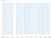
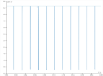
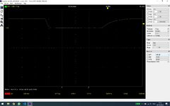
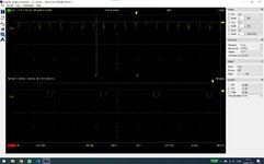
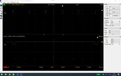
So oscilloscope verifies the signal is good. I've taken three readings at 580ish rpm (idle), 1500 rpm, 3000 rpm. Apologies if the photos aren't in order.

As you can see the frequency is pretty much bang on!

The waveforms aren't 100% perfect - I don't think that's an issue with the signal but rather my shakey hands and doing a poor job holding the probe in the superseal connector whilst trying to operate the oscilloscope and rev the car.

I've sent this data to Chris to see what he says, hopefully it's something they can resolve on their end.
 

Attachments

  • 050DBB0A-BA5B-4529-97F8-820D2CA4BEFE.jpeg
    050DBB0A-BA5B-4529-97F8-820D2CA4BEFE.jpeg
    70 KB · Views: 47
  • C959BCC0-6710-4534-99A1-0D7C6338F402.jpeg
    C959BCC0-6710-4534-99A1-0D7C6338F402.jpeg
    71.3 KB · Views: 35
  • 87A4484A-65BF-4221-A4F9-A04DB74AE243.jpeg
    87A4484A-65BF-4221-A4F9-A04DB74AE243.jpeg
    66.3 KB · Views: 52
  • Like
Reactions: wheela

shushikiary

Sergeant
Jun 4, 2018
304
174
0
Ride
335xi
That's a good edge rate, though the pulse width is a little narrow, which may be the problem. The reflex may not like how short the pulse width is on the "off" side I bet.

It would be nice if Motiv would give us the spec for that. Likely they are using a built in peripheral for the SOC they chose, likely a comparator/counter/timer, and the spec sheet for the SOC will give us the details on what it expects as far has where the trigger point is voltage wise and the required minimum duration (hold time) to trigger.


I just had a thought.... I don't know what ECU you're using but many ECU's have an "RPM out" pin that will give you a perfect square wave at 50% duty cycle at the frequency of the motor. Using that pin, if you have it, may be a quick solution.
 
Last edited:
Feb 21, 2022
25
2
0
That's a good edge rate, though the pulse width is a little narrow, which may be the problem. The reflex may not like how short the pulse width is on the "off" side I bet.

It would be nice if Motiv would give us the spec for that. Likely they are using a built in peripheral for the SOC they chose, likely a comparator/counter/timer, and the spec sheet for the SOC will give us the details on what it expects as far has where the trigger point is voltage wise and the required minimum duration (hold time) to trigger.
I think that's the most likely scenario so far. It is a shame that all the details are closed source.
 

shushikiary

Sergeant
Jun 4, 2018
304
174
0
Ride
335xi
So you've got your full 5v, a 40uS hold time isn't all that short. A rise time from 0-5v of 10uS however is pretty slow on that back end. The fact that you have no overshoot means you're likely not inductive and mostly capacitive for your impedance, at least at this edge rate. Likely a product of long wires.

I assume you're measuring this at the ECU?

Almost nothing newer these days has a hold time that is longer than 40uS, and that edge rate isn't so bad most things wouldn't pick it up either, even if it is rather slow. So unless they are firmware polling a pin, or maybe trying to use an ADC that is not setup right (like trying to sample each pin rather than setting all pins to sample at once and then reading them all at once, which would make the sample rate WAY too slow with a 12 pin ADC for example). I don't know why this signal wouldn't work.

We'd need details on exactly how they did this in the Reflex.
 
Feb 21, 2022
25
2
0
So you've got your full 5v, a 40uS hold time isn't all that short. A rise time from 0-5v of 10uS however is pretty slow on that back end. The fact that you have no overshoot means you're likely not inductive and mostly capacitive for your impedance, at least at this edge rate. Likely a product of long wires.

I assume you're measuring this at the ECU?

Almost nothing newer these days has a hold time that is longer than 40uS, and that edge rate isn't so bad most things wouldn't pick it up either, even if it is rather slow. So unless they are firmware polling a pin, or maybe trying to use an ADC that is not setup right (like trying to sample each pin rather than setting all pins to sample at once and then reading them all at once, which would make the sample rate WAY too slow with a 12 pin ADC for example). I don't know why this signal wouldn't work.

We'd need details on exactly how they did this in the Reflex.
Yep.. very baffling.

The connection is soldered at the ECU end, and I'm taking the signal from the superseal connector on the reflex. I believe the OEM cabling essentially wraps around the engine to the G28 sensor, so overall quite a long connection but I've minimised it as far as possible without going under the car and running it directly from the sensor.

Chris is also pretty baffled - I'm not sure who exactly on the team handles the firmware and hardware side of things. It's a long process of going back and forth. They sent me new firmware last night but the same problem occurs.

Do you know of anyone that has obtained similar data from one of the BMW vehicles? It would be good to compare but I'm not seeing much online.
 
Feb 21, 2022
25
2
0
Motiv are thinking the issue is with the voltage output by the crankshaft sensor. They're expecting it to drop close to 0v but are seeing .25v-.38v.

Checked the resistance of the ground pin and on all ground points tested it's reading below 1 Ohm.
 

shushikiary

Sergeant
Jun 4, 2018
304
174
0
Ride
335xi
0.25v is WELL within noise margin. TTL is typically anything below 1.2v and CMOS is anything below 0.8v, and you're well under that.

It would be one thing if your low end was 0.75v or something, but 0.38v "shouldn't" be a problem.

You could put what they call a "buffer" in-between the two.

AKA, if you put the output of sensor into a buffer IC and then its output into the Reflex it would likely give you not only faster edge rates but also give you a better low voltage.

That or use a scmitt trigger.
 
Feb 21, 2022
25
2
0
0.25v is WELL within noise margin. TTL is typically anything below 1.2v and CMOS is anything below 0.8v, and you're well under that.

It would be one thing if your low end was 0.75v or something, but 0.38v "shouldn't" be a problem.
That's good to know. I appreciate the information, I'm learning a lot.

Chris has told me they've got a hardware fix but they're looking to exhaust any possibilities that it's a wiring issue or something on my end.
 

shushikiary

Sergeant
Jun 4, 2018
304
174
0
Ride
335xi
It's very likely they have a over voltage/negative voltage/ESD protection circuit on the board for all the inputs, it's possible that it's eating into some of the margin for the SOC's voltage margin, especially if they are on separate grounds (which is a good thing for noise decoupling), but unless you're using an optoisolator that can cause some strange things to happen sometimes, or eat into margin like this.

If I was you, I'd jump to nuclear option and throw a schmitt trigger on the thing using a bread board and your own 5v power supply tied to the same ground as the reflex.
 
Feb 21, 2022
25
2
0
It's very likely they have a over voltage/negative voltage/ESD protection circuit on the board for all the inputs, it's possible that it's eating into some of the margin for the SOC's voltage margin, especially if they are on separate grounds (which is a good thing for noise decoupling), but unless you're using an optoisolator that can cause some strange things to happen sometimes, or eat into margin like this.

If I was you, I'd jump to nuclear option and throw a schmitt trigger on the thing using a bread board and your own 5v power supply tied to the same ground as the reflex.

As per Chris,

"the last set of logs you sent from the O scope were very clean and clear. We use a very high quality high freq input drive so that it doesnt skew or add any floating voltage to the signals. If there was an issue we would 100% see it on our bench or on other cars that drop to 0v. The B58 sensor is pretty touchy and if the Reflex isnt grounded well you get a rotation implausibility because it changes how the wave form is picked up. But the newest ones we use are top notch and dont cause any issues even with a not so great ground.

But we dont technically do any pull down since the ECU/DME does that. we just piggy back off the signal in the least invasive way we can."

I think it's looking like I'll get a third reflex sent out (yay for international postage, lol) and fingers crossed that should clear it up. I was considering adding my own signal processor inline just for the fun of doing so, but this saves me experimenting with that at least.