WOW, this is such good information, thank you.I've been lurking on this forum for a while, but have been in the community for many years. I was on a different forum a few years back but it devolved into a mess and most people came here. I just took a break from forums for a while. I am also an electrical design engineer so I have some insight here.
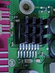
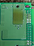
From the back of the board you can clearly see where the heat is being generated. For it to get discolored like that it is getting pretty warm. The part in question is a motor driver and that is what is going to dissipate all of the power. Pretty obvious.
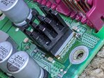
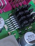
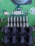
Your approach to slap a heatsink on the top of the package is logical, but the thermal resistance from the package die (the silicon die inside the part where the power is being dissipated) is much lower to the board than it is to the top of the package. The part has an exposed pad under it ("pin" 8 in the datasheet) specifically to help get the heat out. You can clearly see a lot of heat is being transferred to the board. That's one of the reasons there are so many vias in the board under the driver. You can see that copper pad on the underside has no connection electrically. It is there to help transfer heat.
I would focus on transferring the heat from the board to the aluminum plate. You can see the part is already designed to do that. Heat gets transferred to the board and then through the gap pad and into the plate where there is a raised area to ensure good contact and a recessed area to prevent interference with parts on the bottom of the board. I would change out that pad with the same thickness pad with a higher thermal conductivity (W/m*k) rating.
Check digikey.com, but watch the "Usage" column. Some of the newer graphite pads are designed to conduct heat in mainly one direction (through plane vs. in plane). Also, graphite is conductive so it would be a poor choice for a PCB. I would just exclude it from the "Type" column and then sort descending by "Thermal Conductivity". Pick one of the right size and thickness.
I would also attach a large heatsink to the aluminum plate and mount the EKP upside down. Orient the fins vertically so convection currents can form. You may or may not need a fan this this solution. Use some non threaded spacers to avoid crushing the plastic case. A new bottom section made from a piece of Al with heatsink fins milled in would be best, but putting a larger heatsink on the aluminum base is second best. Use some CPU thermal compound between the plate and the heatsink along with the new thermal pad between the board the the plate as mentioned above.
Old CPU coolers look like they would be just about the right size to mount on the plate, and they already come with 12V fans. You could attach one with screws to the EKP plate. You should be able to pick up 12V through terminal 30G, the power supply to the module. I think that is switched with the ignition.
I notice the BTN7960 is discontinued. I wonder if pin-for-pin compatible parts exist that have less loss and higher continuous current specs. Those big parts are easy to replace.
[EDIT] BTN8982 replaces BTN7960, is pin for pin compatible, has lower on state resistance and has higher current carrying capabilities. https://www.infineon.com/cms/en/search.html#!view=discontinued&term=BTN7960
Regarding replacing the BTN8982 with BTN7960, how much of a difference would this make?
I mean is this a marginal change or would it make a big difference?
Also this looks like a good replacement pad. https://www.newegg.com/arctic-cooli...mal_pad-_-35-186-163-_-Product&quicklink=true
I have a spare EKPM3 I am willing to test this with.
Last edited:


