DIY Charging Supply PSU for ISTA+ BMW Programming

fmorelli

Lieutenant General
Staff member
Aug 11, 2017
3,764
3,624
0
58
Virginia
Ride
E89 Z4 35i, F10 535d
Good feedback. Unfortunately amperage requirements are higher on the later cars.

We are using a trim resistor so I can play with current setting. I've read there are some workarounds to increase current ceiling?

I'll report back after more testing.
 

mc-3

New Member
Jan 11, 2022
1
0
0
Hi guys, fantastic job! you inspired me and I just ordered the Dell 1570 to do this. I'm coding on my BMW motorcycle, so maybe overkill, but rather do that than fall short.
One minor question is the 91ohm resistor. Do I really need it or can I get away with a simple connector?
 

fmorelli

Lieutenant General
Staff member
Aug 11, 2017
3,764
3,624
0
58
Virginia
Ride
E89 Z4 35i, F10 535d
@NoQuarter any feedback on the 91Ω resistor? I am running my setup and that's what we have there.

It works generally fine. I'm not holding voltage quite as high as I'd like, but it's high enough that ISTA+ seems happy. I've used it several times on my E70 X5 without issue.
 

NoQuarter

Major
Nov 24, 2017
1,662
1,066
0
Indiana, USA
Ride
Z4 35is, 535xi, X5 35i
That resistor is required in order to get the voltage to adjust higher.

And... it needs to be an adjustable trim resistor so it can be set to a more precise value that works for the specific psu..

I can't get my voltage as high as I prefer either without it going into safe mode and shutting down. One last thing I thought to try was to use a really low range trim resistor so there would be wide range of adjustment around that 91 ohm value.
 
  • Like
Reactions: fmorelli

Heffstar

New Member
Nov 18, 2023
1
0
0
Reviving an old thread. This looks amazing. What ever happened to it? I could seriously buy this lol.
 

larsony99

New Member
Mar 4, 2024
1
0
0
I am here referencing this thread in 2024, and not an electrical engineer. What did everyone find out regarding the resistors and voltage and overcurrent protection?
 

Nexus665

New Member
Dec 2, 2024
4
3
0
Hi,

not sure if @fmorelli is still watching this thread, but still wanted to post my observations and caveats.

First, let me say that most of this project is excellent and very well documented. However, there is one thing about it which does not sit quite right with me.

You chose components with safety margins for most things. Why then did you specify 8AWG/10AWG load wiring for an 80A DC load? Why even use a thinner gauge on the inside from PSU to shunt? I'm scratching my head and not coming up with a logical reason for this choice.

That is WAY too little for a sustained DC load of that size - and may contribute to the voltage drop some have reported. The PSU itself regulates the load very, very well, with little dropoff. I am aware that this load while doing updates is not continuous, still, always plan for worst case scenarios in EE designs.

IMO - and I'm basing this on many available online calculators as well as my EE college course book - for an 80A sustained DC load, you should use ~25 mm^2 conductor area, being about 3AWG!

That is a HUGE difference, 3x the conductor area of 8AWG.

The cable in your photos look more like 3AWG than 8AWG, as well - it's pretty fat, my 8AWG is tiny in comparison using the same copper adapter plate from the plans.

So I think this may have been a transcription error somewhere maybe - but IMO, if you use a larger conductor diameter for the load side, you will have a much better experience actually using the PSU for its intended purpose - to flash without headaches.

Finally, as a bonus for people who actually read, about that resistor between D3 and D4:

Think of no connection between the pins (default state of the PSU) as a resistor with infinite Ohms. PSU Output: ~12V

Now, when you use a jumper cable between these pins, think of that as a resistor with 0 Ohms. PSU Output: 0V.
Why? Because the OVP (Over Voltage Protection) circuit kicks in immediately and shuts the PSU down.

Neither of these will give you the desired effect of reaching ~13.8V under load. To reach that, you will have to find the right resistance value for your PSU (they do differ a bit, it seems) to reach your desired value.

To make it easier on yourself, try using say a 100 or 150 Ohm resistor wired in parallel to any trim pot (preferrably 1-10kOhm) you have lying around. Adjust the trim pot to its highest resistance, connect it to pin D3 and D4. At the highest setting, you will basically get the value of the parallel resistor, and you can fine-adjust the resistance pretty neatly. Always double-check with a Multimeter! Don't use values below about 80 Ohms, or your PSU probably will not start/shut down immediately.

My PSU needed 114 Ohms between D3 and D4 to have a no-load voltage of 13.91V. Will have to test load regulation when I'm done with the case ^^ May need to retrim the voltage then, happy for now.

<edit>spelling ^^</edit>
 
Last edited:
  • Like
Reactions: fmorelli

Nexus665

New Member
Dec 2, 2024
4
3
0
After further testing, I have some more observations - the PSU actually does have considerable (.3-.4V) voltage drop under the proposed load, more than I had experienced with previous server PSU mods using a Delta DPS-2000BB.

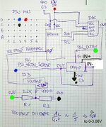
So I am working on a fix for that, will post it here. It involves using an Arduino (smallest is sufficient) and a DAC chip. Should have stable output voltage under any load then - and not overshoot on idle, either! Both are readily available for <20 USD total combined.

This means that on startup, the PSU will boot with a safe setting, then the Arduino will regulate it to the desired value and keep it there. Could do that with a purely passive solution (without a controller), but that's really more work to get right than a few lines of code ^^

If it helps someone, nice, if not, I'm doing it anyway - merry Christmas :D
 
  • Like
Reactions: wheela

Nexus665

New Member
Dec 2, 2024
4
3
0
Sorry for the double post, but check this out -


And yes, I was listening to/watching a Warhammer 40K lore video in the background ^^

Next up: load tests and fine-tuning, if necessary - but since it's really simple, should not take much. Using an Arduino Pro Micro (Mini or other Arduino is sufficient), an MCP4725 DAC breakout board and any OpAmp you have lying around that can take 15+ V input voltage.

Doesn't have to be these components, but they are available as pre-soldered breakout boards that you just wire up with jumper cables, minimal soldering required. I used what I had lying around, an LM324M quad rail-to-rail OpAmp. Doesn't have to be, normal ones are sufficient.

Arduino cost 10 Euros, DAC board costs 2-5 Euros, OpAmp costs a few cents. Couple resistors and pins, jumper cables - sub 20 USD total as stated.

There are even Arduino boards with a DAC included, the cheapest one of those costs about 25 Euros/USD. You'll still need an OpAmp to drive the PSU sense circuit, the DAC cannot supply enough power on its own, it's not meant to drive a load, just to generate an accurate voltage.

Here's a simplified schematic that should give the general idea, no output filtering yet, seems to work nicely anyway.
Enjoy! Will post finished version when I get around to it.
<edit>First version had a silly mistake, happens when you just jot it down quickly on a pad without double-checking. IN+ and IN- were mixed up, forgot to add IN+ in the first place...fixed. KiCad Schematic and board incoming.

Simplified_Schematic.jpg
<edit 3>
I created a new thread for this sub-project, all info is there.
 
Last edited:
  • Like
Reactions: wheela