Hi,
not sure if
@fmorelli is still watching this thread, but still wanted to post my observations and caveats.
First, let me say that most of this project is excellent and very well documented. However, there is one thing about it which does not sit quite right with me.
You chose components with safety margins for most things. Why then did you specify 8AWG/10AWG load wiring for an 80A DC load? Why even use a thinner gauge on the inside from PSU to shunt? I'm scratching my head and not coming up with a logical reason for this choice.
That is WAY too little for a sustained DC load of that size - and may contribute to the voltage drop some have reported. The PSU itself regulates the load very, very well, with little dropoff. I am aware that this load while doing updates is not continuous, still, always plan for worst case scenarios in EE designs.
IMO - and I'm basing this on many available online calculators as well as my EE college course book - for an 80A sustained DC load, you should use ~25 mm^2 conductor area, being about 3AWG!
That is a HUGE difference, 3x the conductor area of 8AWG.
The cable in your photos look more like 3AWG than 8AWG, as well - it's pretty fat, my 8AWG is tiny in comparison using the same copper adapter plate from the plans.
So I think this may have been a transcription error somewhere maybe - but IMO, if you use a larger conductor diameter for the load side, you will have a much better experience actually using the PSU for its intended purpose - to flash without headaches.
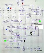
Finally, as a bonus for people who actually read, about that resistor between D3 and D4:
Think of no connection between the pins (default state of the PSU)
as a resistor with infinite Ohms. PSU Output: ~12V
Now, when you use a jumper cable between these pins, think of that
as a resistor with 0 Ohms. PSU Output: 0V.
Why? Because the OVP (Over Voltage Protection) circuit kicks in immediately and shuts the PSU down.
Neither of these will give you the desired effect of reaching ~13.8V under load. To reach that, you will have to find the right resistance value for your PSU (they do differ a bit, it seems) to reach your desired value.
To make it easier on yourself, try using say a 100 or 150 Ohm resistor wired
in parallel to any trim pot (preferrably 1-10kOhm) you have lying around. Adjust the trim pot to its highest resistance, connect it to pin D3 and D4. At the highest setting, you will basically get the value of the parallel resistor, and you can fine-adjust the resistance pretty neatly. Always double-check with a Multimeter! Don't use values below about 80 Ohms, or your PSU probably will not start/shut down immediately.
My PSU needed 114 Ohms between D3 and D4 to have a no-load voltage of 13.91V. Will have to test load regulation when I'm done with the case ^^ May need to retrim the voltage then, happy for now.
<edit>spelling ^^</edit>


