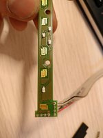
Yet another CAN module - Shiftlights, MDrive, NBT and more

Xantor

Private
Jan 3, 2023
43
5
0

RSL

Lieutenant
Aug 11, 2017
937
501
0
I had asked @Jake@MHD to add message logic in MHD a long while ago for non-CAN module functionality, but it seems to have fallen by the wayside. The message is 0x206 2 bytes.

First byte: 0xXY
X: part of sequence speed
Y: 5 = OFF, 6 = ON, A = Flash

Second byte: appears to be combined with B0 bit X for 0-FFE sequence interval from my testing.

ex. 0x206 {0x86, 0x00} will light segments 0.8 secs apart when sent.

I was able to inject on K or PT when I tested.
 

superwofy

Corporal
Jan 18, 2021
126
190
0
Fixed so that it would be relevant. The question to Superwofy.

I was wondering how does COMFORT_EXIT work?
Do you just move seat back once driver door open was detected?
How does seat move back to preprogrammed position? (I noticed that it can move only on door open or unlock)

It works by sending a move driver's seat back job when Terminal R is switched off and then the door is opened. It essentially emulates the top seat movement button for 3s.
You then exit the car, close the door and lock it. When you unlock, the seat moves back to the last memory position.
The feature is disabled if the move seat back option isn't ticked on iDrive.

Indeed it's not fully reliable since I cannot control memory settings directly or at the very least I haven't found a way to.
For example, if you turn Terminal R off, open the door, close it back and start the car, the seat will still be in the EXIT position.

Thank you for that however that’s code but I’m not seeing the specific can messages and addresses

I'm adding the 206 message file in the next commit. See here the contents of it:
Code:
16:19:27.844 -> Standard ID: 0x206       DLC: 2  Data: 0x86 0x3E        // Each one of these messages turns on one segment including reds
16:19:28.013 -> Standard ID: 0x206       DLC: 2  Data: 0x86 0x3E
16:19:28.115 -> Standard ID: 0x206       DLC: 2  Data: 0xB6 0x00        // Turns on segments sequentially all the way
16:19:28.251 -> Standard ID: 0x206       DLC: 2  Data: 0xB6 0x00
16:19:28.421 -> Standard ID: 0x206       DLC: 2  Data: 0xB6 0x00
16:19:28.930 -> Standard ID: 0x206       DLC: 2  Data: 0x05 0x00        // OFF
16:19:29.099 -> Standard ID: 0x206       DLC: 2  Data: 0x05 0x00
16:19:29.235 -> Standard ID: 0x206       DLC: 2  Data: 0x05 0x00


First nibble of the byte specifies speed of operation. 0-F, F slowest
Second nibble is the operation.

Operations:
2, 6, 0xE Sequence,
5 OFF
0xA Flash

Sequential:  0xB6, time between segments (higher number, slower actuation)

It's exactly how @RSL described it.

The repo contains files which show you the EDIABAS job and corresponding CAN frame bytes. It's rather specific.

Nice work, @superwofy.

Glad you like, next commit will bring NBT emulation. So far, the idea has been to use a separate KCAN2 bus from an MCP2515 shield. I am working on trying to reduce the CAN speed on Jacinto to 100kbps. If I manage to do that, it will be glorious since there's no real overlap of messages between BN2010 and BN2000.
 
  • Like
Reactions: Xantor and Hotter

That4chanhackerguy

Specialist
May 27, 2022
67
10
0
It works by sending a move driver's seat back job when Terminal R is switched off and then the door is opened. It essentially emulates the top seat movement button for 3s.
You then exit the car, close the door and lock it. When you unlock, the seat moves back to the last memory position.
The feature is disabled if the move seat back option isn't ticked on iDrive.

Indeed it's not fully reliable since I cannot control memory settings directly or at the very least I haven't found a way to.
For example, if you turn Terminal R off, open the door, close it back and start the car, the seat will still be in the EXIT position.


I'm adding the 206 message file in the next commit. See here the contents of it:
Code:
16:19:27.844 -> Standard ID: 0x206       DLC: 2  Data: 0x86 0x3E        // Each one of these messages turns on one segment including reds
16:19:28.013 -> Standard ID: 0x206       DLC: 2  Data: 0x86 0x3E
16:19:28.115 -> Standard ID: 0x206       DLC: 2  Data: 0xB6 0x00        // Turns on segments sequentially all the way
16:19:28.251 -> Standard ID: 0x206       DLC: 2  Data: 0xB6 0x00
16:19:28.421 -> Standard ID: 0x206       DLC: 2  Data: 0xB6 0x00
16:19:28.930 -> Standard ID: 0x206       DLC: 2  Data: 0x05 0x00        // OFF
16:19:29.099 -> Standard ID: 0x206       DLC: 2  Data: 0x05 0x00
16:19:29.235 -> Standard ID: 0x206       DLC: 2  Data: 0x05 0x00


First nibble of the byte specifies speed of operation. 0-F, F slowest
Second nibble is the operation.

Operations:
2, 6, 0xE Sequence,
5 OFF
0xA Flash

Sequential:  0xB6, time between segments (higher number, slower actuation)

It's exactly how @RSL described it.


Glad you like, next commit will bring NBT emulation. So far, the idea has been to use a separate KCAN2 bus from an MCP2515 shield. I am working on trying to reduce the CAN speed on Jacinto to 100kbps. If I manage to do that, it will be glorious since there's no real overlap of messages between BN2010 and BN2000.
I really appreciate this, I know it might be a while till we see this make it to MHD or not based on what was shared earlier but ill see if we can add to the reflex since this can be called over PT can
 
  • Like
Reactions: superwofy

Xantor

Private
Jan 3, 2023
43
5
0
Glad you like, next commit will bring NBT emulation. So far, the idea has been to use a separate KCAN2 bus from an MCP2515 shield. I am working on trying to reduce the CAN speed on Jacinto to 100kbps. If I manage to do that, it will be glorious since there's no real overlap of messages between BN2010 and BN2000.
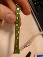
Can you explain the NBT part a bit? So you will emulate a NBT Idrive? Or just some features of it? Sounds interesting to me.

I have seen you implemented the Active Sound Design from an E89 Z4 (?) and a Night Vision / Video Switch logic off a F01 series car. Could this be it?
 
Last edited:

superwofy

Corporal
Jan 18, 2021
126
190
0
Can you explain the NBT part a bit? So you will emulate a NBT Idrive? Or just some features of it? Sounds interesting to me.

I have seen you implemented the Active Sound Design from an E89 Z4 (?) and a Night Vision / Video Switch logic off a F01 series car. Could this be it?

Not much to it, I've added another CAN controller+trasceiver and will run an NBT from that. All messages/formulas etc will be available. Anyone should be able to create an emulator from that.

Yes, I added a bit of logic to mute/unmute the E89 ASD module.
Night Vision is WIP for now, it's sitting on the bench.
The VSW is implemented. I needed that as I ran out of video inputs on the CIC. It's fully working but I will not be using it in the future as my NBT has 4 video inputs.
 
  • Like
Reactions: Xantor and wheela

Xantor

Private
Jan 3, 2023
43
5
0
Dang that brought up many questions.
-Will this be a Nbt or an evo?
-Does this mean you'd scrap the mdrive logic on your car or does the f series mdrive still work?
-do all e series features work with the Nbt?
-would coding and diagnostics be via ethernet/ e sys?
- do you use an emulator for that?
 

superwofy

Corporal
Jan 18, 2021
126
190
0
Dang that brought up many questions.
-Will this be a Nbt or an evo?
-Does this mean you'd scrap the mdrive logic on your car or does the f series mdrive still work?
-do all e series features work with the Nbt?
-would coding and diagnostics be via ethernet/ e sys?
- do you use an emulator for that?

- NBT, non-evo.
- No, F series will work.
- In principle no since it's not designed for them. But the only thing I've found so far that can't be hidden away or emulated is the car 3D models.
- Yes.
- This is the "emulator".
 

Xantor

Private
Jan 3, 2023
43
5
0
Oh thanks for your quick reply. I thought youd use an existing emulator and build your base around that. Amazing work!
I think I have seen somewhere that the 3d car models can be modified somehow. Some guy here in Germany (IG: @S55_m4) has his car with his wrap in his Idrive so there must be a way to modify them.
I have seen you've worked on an CIC portal as well so you might be familiar with the structure around the files.

Looking forward to see the first spoiler videos or pictures with the nbt installed.

Mind me asking what your main goals are besides having a better Infotainment? Like 360° Camera view or a working web-browser?
 

superwofy

Corporal
Jan 18, 2021
126
190
0
Oh thanks for your quick reply. I thought youd use an existing emulator and build your base around that. Amazing work!
I think I have seen somewhere that the 3d car models can be modified somehow. Some guy here in Germany (IG: @S55_m4) has his car with his wrap in his Idrive so there must be a way to modify them.
I have seen you've worked on an CIC portal as well so you might be familiar with the structure around the files.

Looking forward to see the first spoiler videos or pictures with the nbt installed.

Mind me asking what your main goals are besides having a better Infotainment? Like 360° Camera view or a working web-browser?

That's EVO. The car image in that is just a png as far as I am aware. NBT images are somehow embedded in a file "images-vehicle.db". If I figure it out it will be posted in the NBT Development forum.

Yes I built the portal however, it's not related unfortunately. As a side note, I will be adapting the portal for NBT too.

I wanted the faster UI and USB video. That's all it provides really. Potentially better integration with NiVi2/3 also, whenever I get around to that...
 
  • Like
Reactions: Xantor

Xantor

Private
Jan 3, 2023
43
5
0
Do you plan on using the touch Idrive Controller as well?

I reckon the nbt retrofit is still ongoing. Will you share some details or possibly even a DIY on how you did it? I kinda want to mirror your car tech techwise.
Despite the fact that mine's an E93 we share a lot of extras so it'll be a bit easier for me than for others probably.

I have seen that the F80 Mdrive has 3 options for the servotronic - comfort, Sport / (+). Will this still work with your svt70 setup as it only has a comfort and sport curve? And does the NBT and CIC share the same IDs and Data regarding the Mdrive?

I am new to retrofitting F-Series stuff to E-Series cars but would the NBT and Nivi for example show up on ISTA in the ECU tree?

Oh and what I also wondered is if a HUD would work with the NBT in place. I know it gets its data for navigation from it. It's also connected to the DSC/ DME if I remember correctly. As it is smaller, maybe it would clear the E9x dashboard. But I don't think the data sent from the DME and DSC are the same on a F series car (rpm, gear [we have manual anyway] etc.).

What I also saw are F series seat retrofits to E9x cars. The F83 M4 vert utilizes a neckwarmer for the first time which is wired via lin bus to the roof control block in the middle. I think there's a small ECU for it under the rear seats also. Maybe one could make it work? The CTM would probably be mad if one plugged in the F8x roof operation block I assume.

Happy to hear your opinion.
 

Xantor

Private
Jan 3, 2023
43
5
0
Do you happen to have KWP2000 commands for the cruise control display (the moving ring). I have a new idea for your module I want to test.
The idea is that there's two modes. One enables the cruise control display to do what it's intended for, the other uses the indicator to display the engine coolant temp. As there's no other easy way to read the coolant temp.
 

Xantor

Private
Jan 3, 2023
43
5
0
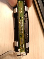
- Is the Mosfet in the middle only used for the exhaust diode?
- In your requirement list you list one 390 Ohm resistor. On the pcb of the buttonblock you marked two with red crosses, does that mean I need two?


1701119870775.png
 

Xantor

Private
Jan 3, 2023
43
5
0
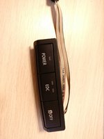
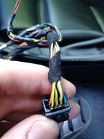
oh and I have the following questions - again. I am having trouble to decipher what pin has which function. Is the following correct?

x4444 pin assignment
As you wrote in a PM some months ago there are no real wiring
diagrams available. So with the resources you sent me and what I could gather
from your Repository, I noted down the following;

Pin 1: Ground

Pin 2: Terminal 58g (is that a signal that dims the leds if you
change the brightness?)

Pin 3: Light for the Power button. You use Digital pin 3 from your teensy.

Pin 4: Power button switch: You use digital output 2 from your teensy.

Pin 5: NOT USED

Pin 6: DSC Button. You use Digital Pin 16 on your teensy to listen for event changes probably.

Pin 7: EDC Button. This is connected to the Junctionbox. I couldn't find
any pin assignments on newTis from an E92 M3 to where that connects exactly. It is a PWM signal to my understanding.

Pin 8: EDC button left light (12V
Pin 9: EDC Button right light (12V) They both connect to the JBE somewhere.

Pin 10: NOT USED
 

That4chanhackerguy

Specialist
May 27, 2022
67
10
0
It works by sending a move driver's seat back job when Terminal R is switched off and then the door is opened. It essentially emulates the top seat movement button for 3s.
You then exit the car, close the door and lock it. When you unlock, the seat moves back to the last memory position.
The feature is disabled if the move seat back option isn't ticked on iDrive.

Indeed it's not fully reliable since I cannot control memory settings directly or at the very least I haven't found a way to.
For example, if you turn Terminal R off, open the door, close it back and start the car, the seat will still be in the EXIT position.


I'm adding the 206 message file in the next commit. See here the contents of it:
Code:
16:19:27.844 -> Standard ID: 0x206       DLC: 2  Data: 0x86 0x3E        // Each one of these messages turns on one segment including reds
16:19:28.013 -> Standard ID: 0x206       DLC: 2  Data: 0x86 0x3E
16:19:28.115 -> Standard ID: 0x206       DLC: 2  Data: 0xB6 0x00        // Turns on segments sequentially all the way
16:19:28.251 -> Standard ID: 0x206       DLC: 2  Data: 0xB6 0x00
16:19:28.421 -> Standard ID: 0x206       DLC: 2  Data: 0xB6 0x00
16:19:28.930 -> Standard ID: 0x206       DLC: 2  Data: 0x05 0x00        // OFF
16:19:29.099 -> Standard ID: 0x206       DLC: 2  Data: 0x05 0x00
16:19:29.235 -> Standard ID: 0x206       DLC: 2  Data: 0x05 0x00


First nibble of the byte specifies speed of operation. 0-F, F slowest
Second nibble is the operation.

Operations:
2, 6, 0xE Sequence,
5 OFF
0xA Flash

Sequential:  0xB6, time between segments (higher number, slower actuation)

It's exactly how @RSL described it.


Glad you like, next commit will bring NBT emulation. So far, the idea has been to use a separate KCAN2 bus from an MCP2515 shield. I am working on trying to reduce the CAN speed on Jacinto to 100kbps. If I manage to do that, it will be glorious since there's no real overlap of messages between BN2010 and BN2000.
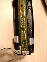
can the lights be triggered individually like lets say I wanted to send a warning message for like a misfire persay, would I be able to trigger the first 2 then only the last 2 red leds?
 

superwofy

Corporal
Jan 18, 2021
126
190
0
oh and I have the following questions - again. I am having trouble to decipher what pin has which function. Is the following correct?

x4444 pin assignment
As you wrote in a PM some months ago there are no real wiring
diagrams available. So with the resources you sent me and what I could gather
from your Repository, I noted down the following;

Pin 1: Ground

Pin 2: Terminal 58g (is that a signal that dims the leds if you
change the brightness?)

Pin 3: Light for the Power button. You use Digital pin 3 from your teensy.

Pin 4: Power button switch: You use digital output 2 from your teensy.

Pin 5: NOT USED

Pin 6: DSC Button. You use Digital Pin 16 on your teensy to listen for event changes probably.

Pin 7: EDC Button. This is connected to the Junctionbox. I couldn't find
any pin assignments on newTis from an E92 M3 to where that connects exactly. It is a PWM signal to my understanding.

Pin 8: EDC button left light (12V
Pin 9: EDC Button right light (12V) They both connect to the JBE somewhere.

Pin 10: NOT USED

This should help:

Yes 58g is the backlight. And it does indeed dim. It does not affect the status LEDs.

EDC is a simple ground switch. The LEDs are PWM'd from the JBEs MCU. That allows it to control servotronic as well - they just changed the duty cycle.
 

Attachments

  • IMG_20210530_154855.jpg
    IMG_20210530_154855.jpg
    181 KB · Views: 22
  • IMG_20210530_154831.jpg
    IMG_20210530_154831.jpg
    233.5 KB · Views: 23
  • IMG_20210530_154827.jpg
    IMG_20210530_154827.jpg
    198 KB · Views: 19
  • IMG_20210530_154734.jpg
    IMG_20210530_154734.jpg
    258.8 KB · Views: 22
  • IMG_20210530_154723.jpg
    IMG_20210530_154723.jpg
    186.4 KB · Views: 29
  • IMG_20210530_153829.jpg
    IMG_20210530_153829.jpg
    225.7 KB · Views: 24
  • IMG_20210530_153818.jpg
    IMG_20210530_153818.jpg
    232.9 KB · Views: 28
  • IMG_20210530_152254.jpg
    IMG_20210530_152254.jpg
    199.9 KB · Views: 22
  • IMG_20210530_152246.jpg
    IMG_20210530_152246.jpg
    203.7 KB · Views: 21
  • IMG_20210530_152242.jpg
    IMG_20210530_152242.jpg
    190.8 KB · Views: 18
  • IMG_20210530_154859.jpg
    IMG_20210530_154859.jpg
    173.1 KB · Views: 19
  • X4444.txt
    423 bytes · Views: 9
  • Informative
Reactions: Xantor

superwofy

Corporal
Jan 18, 2021
126
190
0
can the lights be triggered individually like lets say I wanted to send a warning message for like a misfire persay, would I be able to trigger the first 2 then only the last 2 red leds?

No, completely counter-intuitively, individual control is not possible.
The best you could do is time a few really quickly then slow it way down. It would be quite inaccurate.

For something critical like a misfire you could do a flash instead. That's more predictable and easy to achieve.
 

Xantor

Private
Jan 3, 2023
43
5
0
Thanks for clearing that up. I have another two questions now:

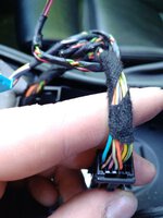
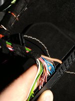
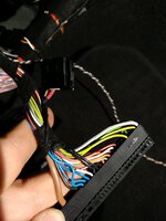
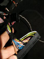
1. Did the blue plug change position after the LCI or why did you mention that? Because there's two versions it seems, one where the blue plug is left and the other where it is right.

2. In regards to your .txt file, PIN 3, 4, 6 are connected directly to your Teensy, right? POWER switch, LED and DSC Switch.