Custom Big Single Turbo upgrade

Dumaurier7

Lieutenant
May 19, 2020
592
256
0
As for figment to the N55…….. it’s a lot easier than building a custom single kit for DAMN SURE! 🤣
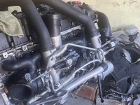
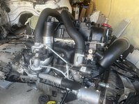
I took a page out of VTT’s book and made an adaptor which avoided me having to drill the head but also gave me much needed room to fit the water pipe to the block as the rear turbine is immediately adjacent. My research led me to decided that the X5’s water pipe is the best shaped one for the job, so I bought 2 and will be doing some custom fab to get the pipe completed but it’s less that 8” of pipe to fab to get that header completed. One more thing! The stock N55 right side motor mount bracket will not work, you will need the one for the S55 as the down pipe from the front turbo will run straight into the N55 one, in my case I also purchased an S55 lower block as mine was smashed so bolt up will not be an issue, for the N55 the boss is there but will have to be drilled and tapped to receive a bolt for attaching point3 of the bracket . Point 4 will remain floating as the N55 block does not have the casting for the boss for the fourth bolt, I plan to just weld in a threaded bung.
 

Attachments

  • IMG_1652.jpeg
    IMG_1652.jpeg
    398.2 KB · Views: 37
  • IMG_1651.jpeg
    IMG_1651.jpeg
    368 KB · Views: 33
Last edited:

Dumaurier7

Lieutenant
May 19, 2020
592
256
0
One more thing ! Came across THIS and bought one ! The price can’t be beat! It is currently en route to a friend in the US who will forward it to CSS for closed deck work.
 
Last edited:

Dumaurier7

Lieutenant
May 19, 2020
592
256
0
A bit more progress, I am successfully fabricating the water pipe from the pump to the block, its tight but it fits, I should have pics up soon. As can be seen the downpipes and F87 Comp right side engine bracket are test fitted as well, the bracket is needed to allow the front downpipe to fit, two of the four bolts, ones on the right, fit, the bung for the one on the lower left is cast into the block but needs to be drilled and tapped. The fourth, which is the left upper is not there, I am currently considering two options which are to weld in a bung to the block or chop off the fourth leg of the bracket and reenforce the SHIT out of it to compensate.


DP1.jpg
DP2.jpg
 

Dumaurier7

Lieutenant
May 19, 2020
592
256
0
preliminary pics of the water pipe fabrication, waiting on another pipe to arrive, I’ll be wrapping it a bit closer around the down-pipe to ensure clearance and for a neater look.

IMG_1682.jpeg
IMG_1680.jpeg
IMG_1679.jpeg

IMG_1678.jpeg
IMG_1677.jpeg
IMG_1676.jpeg
 

Dumaurier7

Lieutenant
May 19, 2020
592
256
0
" in my case I also purchased an S55 lower block as mine was smashed so bolt up will not be an issue, for the N55 the boss is there but will have to be drilled and tapped to receive a bolt for attaching point3 of the bracket. Point 4 will remain floating as the N55 block does not have the casting for the boss for the fourth bolt, I plan to just weld in a threaded bung."
The purchase was cancelled as the NEW N55 block came with the lower bed plate as well, so I'll have to proceeded with my original plans.
 

Dumaurier7

Lieutenant
May 19, 2020
592
256
0
How do you plan to drive the second electronic waste gate?
"The F22 only has one wide band sensor so I’ll be installing it after I Y both down pipes together. plan for the actuators is to simply splice into the existing wires so both will operate in unison, the DME should not have a clue."
If you think about it the S55's DME has no way to know exactly what each turbo is doing other, than the position of each actuator via the internal position switches. in my case, only one actuator will report position as per original design, but the second will mirror the positioning of the first.
 

wheela

Captain
Jun 4, 2021
1,312
750
0
Twin Cities, MN
Ride
2015 e84 X1 35i Msport
If you think about it the S55's DME has no way to know exactly what each turbo is doing other, than the position of each actuator via the internal position switches. in my case, only one actuator will report position as per original design, but the second will mirror the positioning of the first.
Hopefully it won't be a problem, but running two actuators in parallel from the same source will double the current output on the circuit running the actuators. Hopefully it won't fry or shorten the life of the electrical components involved.
 

Dumaurier7

Lieutenant
May 19, 2020
592
256
0
Remember V=IxR! Resistance is only doubled when connected in series but is halved when connected in parallel just like when connecting speakers in a sound system, because there are two coils the resistance goes down so the current drawn will also go down, in fact when in this configuration the total resistance usually adds up to the resistance of one coil. Knowing how smart and bitchy the BMW DME is I have this in mind as a contingency plan!
 
Last edited:

wheela

Captain
Jun 4, 2021
1,312
750
0
Twin Cities, MN
Ride
2015 e84 X1 35i Msport
That's close, but when the curcuit resistance goes down, current goes up if voltage doesn't change. V=IR describes the relationship between current through a circuit based on its total resistance and voltage across it.

Parallel resistance is:
1/Rtotal = 1/R1 + 1/R2 + 1/R3 etc.

If you wire two actuators in parallel, you're correct that the resistance of the circuit is 1/2 that of one actuator. But the voltage supplied by the DME didn't change, so because of V=IR, your total current in the circuit will double. The actuators should work because they'll still see the same supply voltage, but the 2x total circuit current may be hard on the DME.

Series resistance us:
Rtotal = R1 + R2 + R3 etc.

if you wire two actuators in series, the resistance will double as you mentioned. Again the voltage from the DME didn't change, so because of V=IR, the total circuit current will drop in half because resistance doubled. This is safe for the DME, but now the voltage supplied by the DME is dropped across two actuators instead of one. So each actuator only has half the supply voltage accross it instead of the full supply voltage (because V=IR still has to be true accross each actuator). The actuators may or may not still function properly with only half the voltage.

That controller from Full-Race looks sweet! I strongly considered that one for my setup👍
 

Dumaurier7

Lieutenant
May 19, 2020
592
256
0
The voltage is the constant, it will not change, but because they are in. Parallel the resistance remains the same so the current draw remains the same.
 

wheela

Captain
Jun 4, 2021
1,312
750
0
Twin Cities, MN
Ride
2015 e84 X1 35i Msport
The voltage is the constant, it will not change, but because they are in. Parallel the resistance remains the same so the current draw remains the same.
The voltage is constant, but total resistance is cut in half when you add a second identical load in parallel.

Here's some examples. I don't know the control voltage, but since we're in a car let's go with 12 volts. I don't know the resistance of the actuators, but let's assume 50 ohm so we can do some calculations.
 

wheela

Captain
Jun 4, 2021
1,312
750
0
Twin Cities, MN
Ride
2015 e84 X1 35i Msport
Here's the circuit with one actuator. Current with these values is 0.24amp.
 

Attachments

  • Screenshot_20240913_195916_Gallery.jpg
    Screenshot_20240913_195916_Gallery.jpg
    436.3 KB · Views: 5

wheela

Captain
Jun 4, 2021
1,312
750
0
Twin Cities, MN
Ride
2015 e84 X1 35i Msport
Now let's add another identical actuator in parallel. Total resistance drops to 25 ohm, and voltage is still 12 volts. Now current is 0.48amp
 

Attachments

  • Screenshot_20240913_195934_Gallery.jpg
    Screenshot_20240913_195934_Gallery.jpg
    483.4 KB · Views: 6