Here's a quick write-up on how to wire up a spare knock sensor to the block, so your tuner can listen for knock in real time (aka Knock Ears or Det Cans). This is mostly for the built motor peeps experiencing false knock, but could also be helpful for stock motor high power builds with a noisy cylinder 5. Much thanks to @chrisdfv for figuring out the wiring.
Background and Issue:
In 2014 BMS ran into built motor false knock and figured out wiring 100 kOhm trim pots into the knock sensors alleviates the issue. It works, but can be risky if you go too aggressive as it's hardware-level knock signal suppression. If trim pots are being run, the resistance setting would need to be calibrated against real knock. Since the DME is effectively reading permanently desensitized knock sensors, another system separate from the DME is needed for independent knock verification.
A certain "premium" built motor company swears up and down that "our closed deck motors don't false knock". To put it as politely as I can, this is a bald-faced lie. Despite false knock supposedly being a non-issue, this company runs trim pots on their customers' closed deck built motors. Go figure.
You will need:
Steps:
Clean the rear of the spare knock sensor
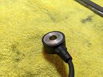
Strip the knock sensor wiring, there will be 2 inner wires white and black if using an N54 sensor.
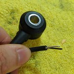
Strip one of the 3.5mm cables that's included with the amp. Solder the knock sensor to the 3.5mm jack.

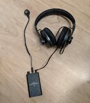
At this point it's a good idea to function test. I found striking the knock sensor against a marble coaster would generate the required force to register a noise in the headphones. Any suitably hard surface will work. Set the amplifier to HIGH gain and maximum volume.

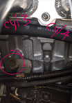
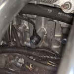
Finally, remove the alternator wire bracket and bolt sensor to block with a M8x1.25 bolt. If you don't want to remove this bracket, there's also an empty threaded hole next to the bank 2 knock sensor.
Background and Issue:
In 2014 BMS ran into built motor false knock and figured out wiring 100 kOhm trim pots into the knock sensors alleviates the issue. It works, but can be risky if you go too aggressive as it's hardware-level knock signal suppression. If trim pots are being run, the resistance setting would need to be calibrated against real knock. Since the DME is effectively reading permanently desensitized knock sensors, another system separate from the DME is needed for independent knock verification.
A certain "premium" built motor company swears up and down that "our closed deck motors don't false knock". To put it as politely as I can, this is a bald-faced lie. Despite false knock supposedly being a non-issue, this company runs trim pots on their customers' closed deck built motors. Go figure.
You will need:
- Spare N54 knock sensor (only one is needed)
- Audio amplifier (I used this one: https://www.amazon.com/gp/product/B07Z1V634H/ref=ppx_yo_dt_b_asin_title_o02_s00?ie=UTF8&psc=1)
- High-quality 3.5mm audio male/female extension cable (I went with 10ft)
- M8x1.25 30mm bolt
- A good pair of over-ear headphones
Steps:
Clean the rear of the spare knock sensor

Strip the knock sensor wiring, there will be 2 inner wires white and black if using an N54 sensor.

Strip one of the 3.5mm cables that's included with the amp. Solder the knock sensor to the 3.5mm jack.
At this point it's a good idea to function test. I found striking the knock sensor against a marble coaster would generate the required force to register a noise in the headphones. Any suitably hard surface will work. Set the amplifier to HIGH gain and maximum volume.


Finally, remove the alternator wire bracket and bolt sensor to block with a M8x1.25 bolt. If you don't want to remove this bracket, there's also an empty threaded hole next to the bank 2 knock sensor.


