To not clutter the DIY Charging Supply for ISTA + BMW Programming thread I decided to post this in its own thread, may be useful for other DIY PSU retrofits as well.
Why do this?
Lots of people have turned to converting server power supply bricks into PSUs for high-power charging their Lipos, for spot welding, for flashing/coding cars, ...
In the thread linked above, forum members put together a very well executed DIY car coding/flashing PSU that supplies 13.8V at high amperage while working on their cars, but found that the output voltage was not really stable, dropping .3-.6V from the 13.8V the BMW docs say should be supplied.
Just turning the no-load voltage up higher so it can hold 13.8V under load is not a great solution. This means 14.4V or more without load, and that's pretty much the upper end of the scale for the chosen PSU, as well as most other server PSUs without hardware mods.
How to make it work
Server PSUs usually have some sort of voltage feedback system, meaning they can be adjusted on the fly. This works by either connecting the sense and 3.3V with a resistor matched to the desired output voltage or directly feeding a voltage to the sense pin - you can use your multimeter to measure the required voltage on both sides of the resistor. That means it is trivial to control via a microcontroller, in this case an Arduino, since they're cheap and widely available.
Required hardware (needs to be 3.3V capable!)
Arduino board - choose one that has a USB port unless you have a serial programmer
DAC breakout board or chip
Operational amplifier (OpAmp) that is single supply 15V input capable, doesn't have to be rail-to-rail, almost anything will work
2.2K and 470 Ohm resistors
Jumper cables
2.54mm/.1 inch solderable pins
Prototype stripboard PCB
Optional: output filtering (coming soon, works fine without so far)
Chosen hardware
Arduino Pro Micro (Leonardo clone in a small format) - available from 5-20 USD, depending on where you buy them
MCP4725 DAC breakout board
LM324-N quad rail-to-rail OpAmp
Software
Arduino IDE (open source and free, Windows, Linux, Mac)
Sparkfun MCP4725 library (click on the library icon on the left and type mcp4725 in the search field, click install)
Connect Arduino to a PC via USB, install drivers for USB serial port if necessary
Be sure to select the board you chose and the correct communications port in the IDE!
Code
This is just a simple hysteresis control loop, no PID. Will do load testing and update code if needed.
It gets a voltage feedback from the PSU output via a voltage divider that scales the voltage to <3.3V for the Arduino. While the output voltage is lower than the setpoint, it will increase it, and lower it if it overshoots (i.e. when the load drops) within a few microseconds (millionths of a second), should be good enough.
Code is documented, upload and test, adjust volt_setpoint if needed. Use quality resistors (1%) if possible, accuracy depends on it.
Circuit board and connections
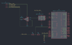
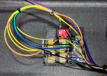
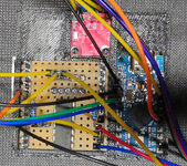
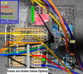
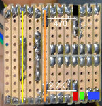
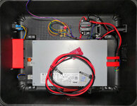
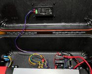
I used some spare stripboard I had lying around, easy to work with. Everything in gold print is supposed to be connected where names match even if you don't see a direct trace.
Other uses
You can use the same design to drive some custom gauges for your simracing setup, simulate sensors, you could even output sound via the DAC. The pro micro board could also easily drive an LCD. It can very probably also be used for other server power supplies with trim pins.
Will post updates as I make them here. In the meantime, merry Christmas and a happy New Year everyone!
Why do this?
Lots of people have turned to converting server power supply bricks into PSUs for high-power charging their Lipos, for spot welding, for flashing/coding cars, ...
In the thread linked above, forum members put together a very well executed DIY car coding/flashing PSU that supplies 13.8V at high amperage while working on their cars, but found that the output voltage was not really stable, dropping .3-.6V from the 13.8V the BMW docs say should be supplied.
Just turning the no-load voltage up higher so it can hold 13.8V under load is not a great solution. This means 14.4V or more without load, and that's pretty much the upper end of the scale for the chosen PSU, as well as most other server PSUs without hardware mods.
How to make it work
Server PSUs usually have some sort of voltage feedback system, meaning they can be adjusted on the fly. This works by either connecting the sense and 3.3V with a resistor matched to the desired output voltage or directly feeding a voltage to the sense pin - you can use your multimeter to measure the required voltage on both sides of the resistor. That means it is trivial to control via a microcontroller, in this case an Arduino, since they're cheap and widely available.
Required hardware (needs to be 3.3V capable!)
Arduino board - choose one that has a USB port unless you have a serial programmer
DAC breakout board or chip
Operational amplifier (OpAmp) that is single supply 15V input capable, doesn't have to be rail-to-rail, almost anything will work
2.2K and 470 Ohm resistors
Jumper cables
2.54mm/.1 inch solderable pins
Prototype stripboard PCB
Optional: output filtering (coming soon, works fine without so far)
Chosen hardware
Arduino Pro Micro (Leonardo clone in a small format) - available from 5-20 USD, depending on where you buy them
MCP4725 DAC breakout board
LM324-N quad rail-to-rail OpAmp
Software
Arduino IDE (open source and free, Windows, Linux, Mac)
Sparkfun MCP4725 library (click on the library icon on the left and type mcp4725 in the search field, click install)
Connect Arduino to a PC via USB, install drivers for USB serial port if necessary
Be sure to select the board you chose and the correct communications port in the IDE!
Code
This is just a simple hysteresis control loop, no PID. Will do load testing and update code if needed.
It gets a voltage feedback from the PSU output via a voltage divider that scales the voltage to <3.3V for the Arduino. While the output voltage is lower than the setpoint, it will increase it, and lower it if it overshoots (i.e. when the load drops) within a few microseconds (millionths of a second), should be good enough.
Code is documented, upload and test, adjust volt_setpoint if needed. Use quality resistors (1%) if possible, accuracy depends on it.
C:
#include <Wire.h>
#include <Adafruit_MCP4725.h>

Adafruit_MCP4725 dac;
unsigned int volt_psu = 0; // 0-1023, 10 Bit resolution on the Arduino
unsigned int dac_out = 0; // 0-4095, 12 Bit resolution on the MCP4725
// Adjust the value of volt_setpoint below to change the output voltage
// Lower number = lower voltage : valid values: 0-1023 -> 750-752 measured for 13.85V output
unsigned int volt_setpoint = 752;

void setup()
{ //I2C address of the DAC - could be 0x60, 0x61 or 0x62, 0x60 is default for MCP4725
  if (dac.begin(0x60))
  {
    // output 0V from the DAC to the 12V_RTN_SENSE pin, no voltage increase for safe startup
    dac.setVoltage(0, false);
  }
  // setup our analog PSU voltage feedback pin
  pinMode(A0,INPUT);
  // wait a bit for PSU and display to start up
  delay(3500);
}

void loop()
{
  // read PSU voltage feedback - ~15mV resolution, i.e. 0.015V - seems good enough
  volt_psu = analogRead(A0);
  // If voltage is less than desired
  if (volt_psu < volt_setpoint ) // Hysteresis of +-1 => ~0.03V
  {
    // limit the max value output to the DAC - should never really reach this value anyway, usually around 2xxx for 13.85V
    if (dac_out < 4095)
    {
      // increase trim/output voltage
      dac_out = dac_out + 1;
    }
    // output the voltage
    dac.setVoltage(dac_out, false);
  }  // if voltage is higher than the setpoint
  else if (volt_psu > volt_setpoint) // Hysteresis of +-1
  {
    // limit to 0 as minimum
    if (dac_out > 0)
    {
      // decrease trim/output voltage
      dac_out = dac_out - 1;
    }
    dac.setVoltage(dac_out, false);
  }
  // delay a short time for the PSU to react - load regulation still needs testing
  delayMicroseconds(10);
}
Circuit board and connections
I used some spare stripboard I had lying around, easy to work with. Everything in gold print is supposed to be connected where names match even if you don't see a direct trace.


Other uses
You can use the same design to drive some custom gauges for your simracing setup, simulate sensors, you could even output sound via the DAC. The pro micro board could also easily drive an LCD. It can very probably also be used for other server power supplies with trim pins.
Will post updates as I make them here. In the meantime, merry Christmas and a happy New Year everyone!

